Wednesday, January 6, 2021

Making a Toy Gyroscope on a Mini-lathe - Part 2


In the previous post I showed how to make the outer cage for a gyroscope toy using a mini-lathe.

In this post I’ll cover how to make the bearing cups, flywheel and spindle, and assemble the parts.

Bearing cups

The bearings are held in two M4 threaded cups which also serve as the balance points for the gyroscope.


Staring with a piece of ⅜” brass rod, face and turn down to about 11mm. Then turn down a 14mm long section down to 4mm. Cut the thread using an M4 die. (I have a die holder for the lathe which makes this easier to get straight, but could be done without):


File the end round and smooth. Cut off the piece and repeat the process for the second cup:


To face and drill the other sides of the bearing cups, I mounted them in a piece of aluminium rod drilled and tapped with an M4 tap to about 12mm depth. Check the measurements of the bearings and drill appropriately:


Finally file some flats on the bearing cups to fit a 10mm wrench. (Alternatively one could use pliers to adjust the cups but this might damage the finish).

Flywheel and Spindle

To start the flywheel, cut a nice thick slug, about 18-20mm thick, off the brass bar. This is the point where I seriously wish I had a bandsaw:


Mount the flywheel in the outer jaws on the lathe and face both sides. Then drill to slightly smaller than the diameter of the spindle rod:

Next we cut a length of rod for the spindle. To determine the length, screw the bearing cups as far as they will go into the inner cage ring. The length should be about 2-3mm more than the maximum distance between the bearing cups (so that the cage will need to be squeezed in the vice in order to assemble).


Turn down a length of the spindle to the diameter of the hole in the flywheel, leaving a collar to center the flywheel on the spindle. The length of the turned section should be (length-of-spindle + thickness of flywheel) / 2.


Next we make a cross-hole in the spindle to use for the string. File a small flat in the thicker end of the spindle and drilling on bench drill:
Next turn down the thicker end of the spindle to the same diameter as the thinner end, leaving a collar for the flywheel. Then turn a length of 1.5-2mm on each end to fit the inside diameter of the bearings:

Now we can insert the spindle into the flywheel, using some green Loctite to set. It should be a tight fit, and, if necessary, you might need to use a vice to push it all the way:
       

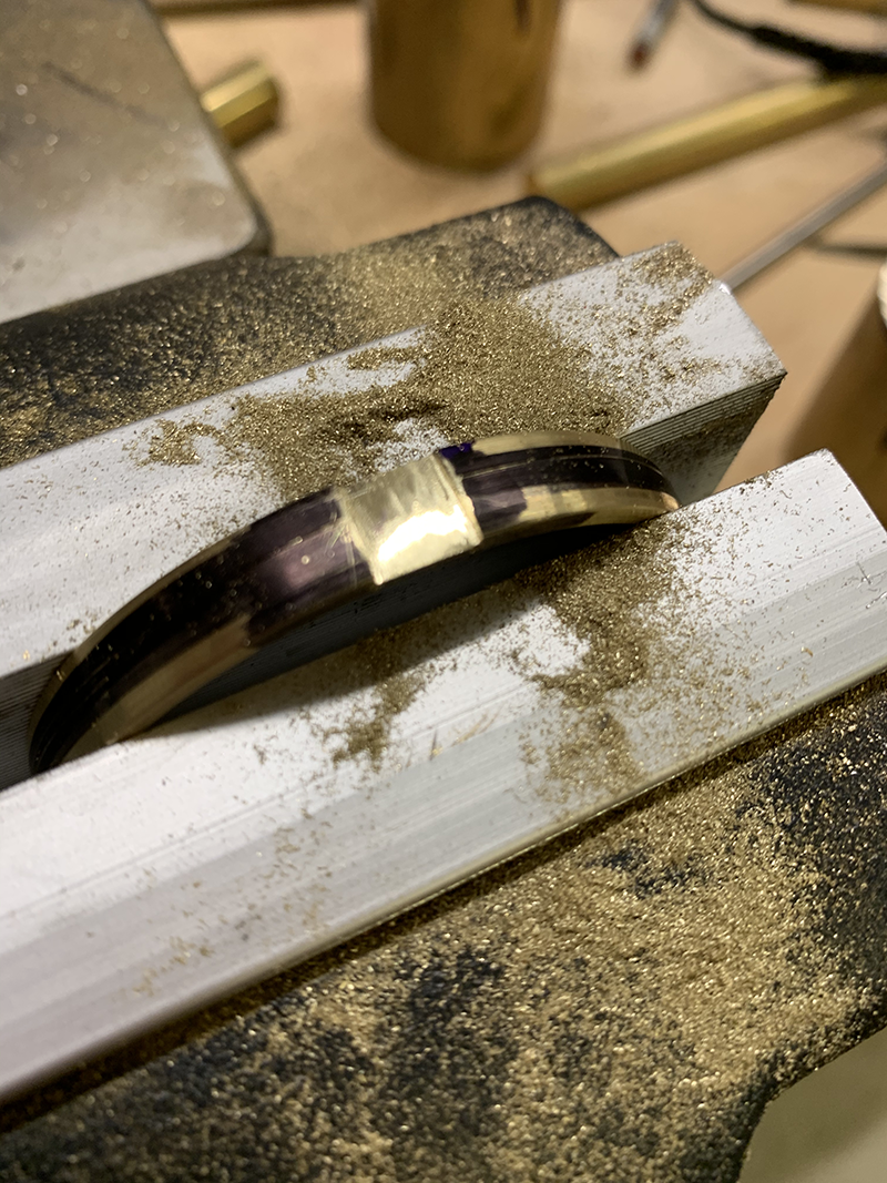
Once the loctite is set, mount the flywheel in the lathe chuck by the spindle. It’s nice to give it a slight “barel-shape” by setting small angles (5 and 10 degrees) on the compound, and finishing with a file and emery paper:

At this point you can choose whether to polish the parts or leave them with a morew “machined” look.

Finishing/Assembly

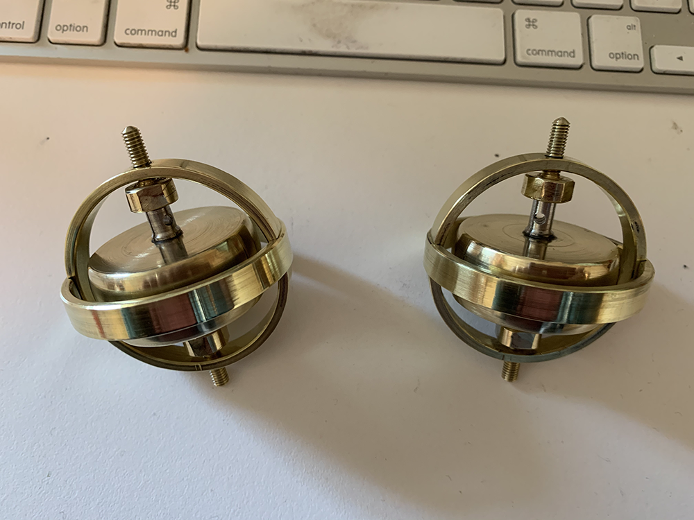
To put it all together, screw the bearing cups into the inner cage, then squeeze the inner cage ring in a vice just enough to fit in the flywheel/spindle/bearings. This squeeze the outer cage ring and fit in the inner-cage/flywheel assembly. Adjust the bearing cups so that there’s little or no play but the freewheel spins freely, and center if needed.


I also made a stand using brass/aluminium and an extension rod to screw onto one of the spindles.


Tuesday, January 5, 2021

Making a Toy Gyroscope on a Mini-lathe - Part 1


(Change of pace for this post.)

Last year I bought myself a Chinese-made mini-lathe (SIEG C3) to play with, similar to the small metal-lathe my father still has in his workshop. I've been doing a few small projects on it, including some spinning tops and simple tools, and decided to try making some toy gyroscopes.


I was inspired by the toy gyroscopes I had when I was a child: you would up a piece of string round the spindle and pulled to get them spinning. They used to come with a little plastic "Eiffel tower" that you would balance them on. I wanted to make something a bit more "serious" than those.

Prototypes

I went through a series of prototypes, starting with some 1 1/2" diameter brass rod. My first attempt didn't have nearly enough angular momentum, so I switched to using much thicker slugs of brass. For the last prototype I bought a piece of 2" brass rod on ebay to use. I also decided they needed an outer cage to allow them to keep spinning when held.


Prototypes

I tried various bearing options, including a simple point-and-cup bearing, miniature thrust bearings and regular cartridge ball bearings. In the end I find that the 1/4" ball bearings purchased from VXB worked best (about $3 each).


This page show the final version I made for my brother's birthday, using a 2" diameter flywheel. I also made a couple of smaller ones for my daughters for Christmas:


Raw materials

The raw materials were:

  • 2" diameter brass round bar for flywheel

  • 2 1/2" OD brass pipe for cage

  • 3/8" brass bar for bearing cups

  • 1/4” stainless rod for spindle

  • 2 X .25" OD/.125" ID bearings


(Note, the dimensions for materials are in inches since that's easier to order in the US. All my working measurements are in metric however, which is much easier to actually work with.)

Part 1: The Cage


The cage is probably the hardest part to make. It consists of two brass rings with notches filed in them to snap together. The inner ring is drilled and threaded for the bearing cups.


First cut two rings from the brass pipe:


Next, face the sides of the two rings and turn them down to 8mm width. Make sure the sides are parallel:


Turn the outside of the pipe off to make it round and get a nice finish:

Now switch to the outside jaws on the chuck, and bore out the inside of the rings to the desired thickness (I did 2.5mm).

Optionally curve the outside surface of the rings. For this switch back to the inside jaws and set the compound to a small angle (5-10 degrees). Finish with a file and emory paper:


Next we need to drill and tap the holes in the inner cage for the bearing cups (M4). It’s important to get these correctly aligned. This could be done with a drill press if you’re very careful, but I found it better and more accurate to drill and tap on the lathe using a 4-jaw chuck:


I also used a tap-follower, which I had made for the purpose, to make sure the tap was straight. You can buy them of course, but they’re easy to make and a nice side project.
Finally we need to file notches in the two rings to make them fit together. These should be the same width as the rings (in this case 8mm) and slightly less than half the thickness of the rings, so that the rings are squeezed/stretched when together. The notches on the inner ring should be 90 degrees from the holes. The sides of the notches on the outside ring should be sloped slightly as they will go in when the ring is squeezed.


We can do a test assembly to make sure the parts fit, and make adjustments if needed.


Put the outer ring in a vise and squeeze until it’s just wide enough to fit in the inner ring:


Continued in ..

(the spinny bits...)