(Change of pace for this post.)
Last year I bought myself a Chinese-made mini-lathe (SIEG C3) to play with, similar to the small metal-lathe my father still has in his workshop. I've been doing a few small projects on it, including some spinning tops and simple tools, and decided to try making some toy gyroscopes.
I was inspired by the toy gyroscopes I had when I was a child: you would up a piece of string round the spindle and pulled to get them spinning. They used to come with a little plastic "Eiffel tower" that you would balance them on. I wanted to make something a bit more "serious" than those.
Prototypes
I went through a series of prototypes, starting with some 1 1/2" diameter brass rod. My first attempt didn't have nearly enough angular momentum, so I switched to using much thicker slugs of brass. For the last prototype I bought a piece of 2" brass rod on ebay to use. I also decided they needed an outer cage to allow them to keep spinning when held.

I tried various bearing options, including a simple point-and-cup bearing, miniature thrust bearings and regular cartridge ball bearings. In the end I find that the 1/4" ball bearings purchased from VXB worked best (about $3 each).
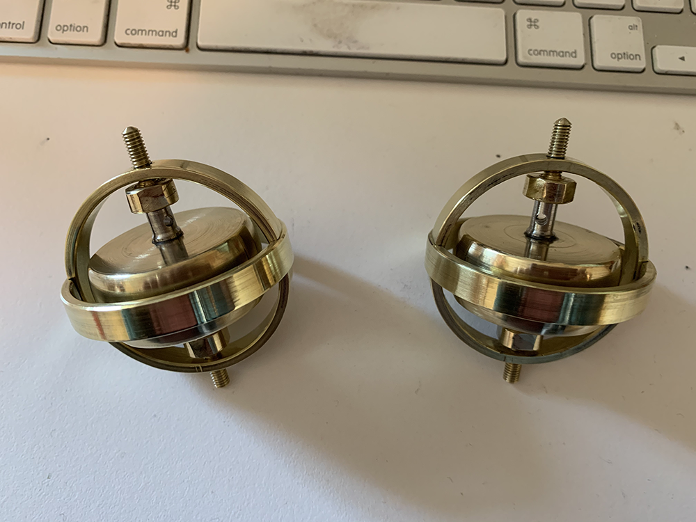
This page show the final version I made for my brother's birthday, using a 2" diameter flywheel. I also made a couple of smaller ones for my daughters for Christmas:
Raw materials
The raw materials were:
2" diameter brass round bar for flywheel
2 1/2" OD brass pipe for cage
3/8" brass bar for bearing cups
1/4” stainless rod for spindle
2 X .25" OD/.125" ID bearings

(Note, the dimensions for materials are in inches since that's easier to order in the US. All my working measurements are in metric however, which is much easier to actually work with.)
Part 1: The Cage
The cage is probably the hardest part to make. It consists of two brass rings with notches filed in them to snap together. The inner ring is drilled and threaded for the bearing cups.
First cut two rings from the brass pipe:

|

|

|

|

|

|

|
Now switch to the outside jaws on the chuck, and bore out the inside of the rings to the desired thickness (I did 2.5mm).

|

|
|

|
Optionally curve the outside surface of the rings. For this switch back to the inside jaws and set the compound to a small angle (5-10 degrees). Finish with a file and emory paper:

|

|

|

|

|

|

|

|
|

|

|
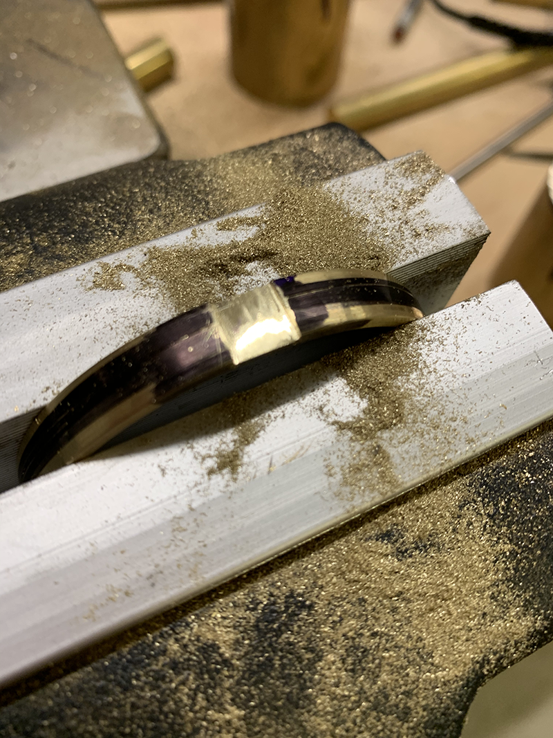
We can do a test assembly to make sure the parts fit, and make adjustments if needed.
Put the outer ring in a vise and squeeze until it’s just wide enough to fit in the inner ring:

|

|
Continued in ..
(the spinny bits...)
No comments:
Post a Comment