In the previous post I showed how to make the outer cage for a gyroscope toy using a mini-lathe.
In this post I’ll cover how to make the bearing cups, flywheel and spindle, and assemble the parts.
Bearing cups
The bearings are held in two M4 threaded cups which also serve as the balance points for the gyroscope.
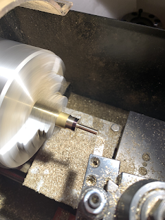
Staring with a piece of ⅜” brass rod, face and turn down to about 11mm. Then turn down a 14mm long section down to 4mm. Cut the thread using an M4 die. (I have a die holder for the lathe which makes this easier to get straight, but could be done without):

|

|

|

|

|

|

|

|

|

|

|

|

|

|
 |
Flywheel and Spindle
To start the flywheel, cut a nice thick slug, about 18-20mm thick, off the brass bar. This is the point where I seriously wish I had a bandsaw:

|

|
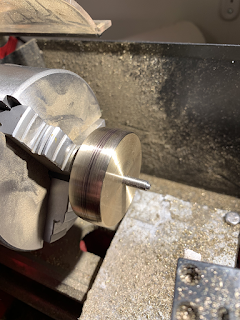
Mount the flywheel in the outer jaws on the lathe and face both sides. Then drill to slightly smaller than the diameter of the spindle rod:

|

|

|

|
Next we cut a length of rod for the spindle. To determine the length, screw the bearing cups as far as they will go into the inner cage ring. The length should be about 2-3mm more than the maximum distance between the bearing cups (so that the cage will need to be squeezed in the vice in order to assemble).
Turn down a length of the spindle to the diameter of the hole in the flywheel, leaving a collar to center the flywheel on the spindle. The length of the turned section should be (length-of-spindle + thickness of flywheel) / 2.

|

|
 |

|

|

|

|

|

|

|
 |
Once the loctite is set, mount the flywheel in the lathe chuck by the spindle. It’s nice to give it a slight “barel-shape” by setting small angles (5 and 10 degrees) on the compound, and finishing with a file and emery paper:

|

|

|

|
At this point you can choose whether to polish the parts or leave them with a morew “machined” look.
Finishing/Assembly
To put it all together, screw the bearing cups into the inner cage, then squeeze the inner cage ring in a vice just enough to fit in the flywheel/spindle/bearings. This squeeze the outer cage ring and fit in the inner-cage/flywheel assembly. Adjust the bearing cups so that there’s little or no play but the freewheel spins freely, and center if needed.
I also made a stand using brass/aluminium and an extension rod to screw onto one of the spindles.


No comments:
Post a Comment